It’s common knowledge that the Rod Rod Deluxe is a fantastic amp, it’s also LOUD. I play live a lot, but almost all my playing is with my amp mic’d and run through a PA, so really need to maintain a manageable stage volume without loosing the sound of driven tubes, especially the sound of saturated power tubes (yum). Plus as much as I like the sound of my playing, when practising the same lick over and over, I don’t know that my wife and kids really want to listen at full volume.
Time to find a solution that didn’t involve buying another amp.
This is a retrospective post from a procedure I undertook about five years ago. I originally documented it on the Amp Garage forums, but you had to be a member to view the documentation, so finally got around to sticking it in a publicly accessible post.
WARNING: The voltages found inside tube amplifiers can and do kill people. If you’re not comfortable working with very high voltages, find someone who is. Seriously, implementing this modification can kill you. Proceed accordingly.
I went down the route of Dana Hall’s VVR power scaling module. From memory it cost about $20 AUD in 2011’ish. At the time of the install, my amp was still under warranty, so wanted an installation that could be reversed with next to no evidence that I’d played inside.
There are two lines the VVR module needs to intercept. The B+ and bias voltage lines.
Finding the B+ intercept point
The simplest way to hook into the B+ line was via two points that already have connectors on the circuit board. In the schematic we see it at the B+ and SP1 points. Note that although they are separate points, they are directly connected.

Here we can see the traces on the back of the board, just to prove that B+ and SP1 are directly connected, as in 0Ω between them.

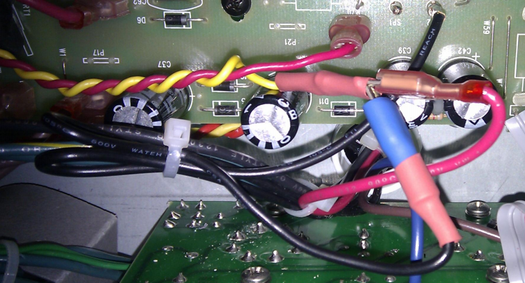
The photo below shoes the front of the board. because B+ and SP1 are connected, we only have to feed one of them to the VVR board. The B+ marked connector wire therefore goes to the B+ IN on the VVR board. Below the black and white image is a colour shot of the same area. The red wire goes to B+ IN, and the yellow comes from B+ OUT, which splits into two and takes the connectors which were originally connected into the amp’s B+ and SP1 points.

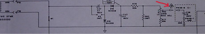
Finding the BIAS intercept point
The intercept point here is C- as shown in the schematic below. Lucky for us at this point the line is moved to another board via a ribbon cable, so easy to hook into.
To break into C-, I slit the end line of the ribbon, to allow it to be isolated. Red goes to BIAS IN on the VVR board, yellow comes from BIAS OUT on the VVR board.

Mounting the VVR board
The board was mounted with the B+ MOSFET onto the base of the chassis as a heat sink, with a mica insulator. The BIAS MOSFET was lifted and isolated, so that it didn’t earth on the chassis. From here lines run up to the potentiometer, mounted in what was the standby switch hole (I hold firmly to the view that the standby switch in guitar amplifiers is a triumph of marketing over engineering). Since the photo below was taken, the standby switch has been removed, and the switch lines jumped with some cable and spade connectors.


The result
It’s been a good five or six years since I installed the VVR, and I remain exceedingly happy with it. Not only would I do it again to my Hot Rod Deluxe, but would also certainly install it into any tube amp I may buy in the future.
Sadly it appears as though Hall Amplifiers who made the VVR module are no longer around. Fortunately London Power still appear to offer kits.

Feel free to leave any questions in the comments.
I’m struggling with understanding how/where to patch in Kevin O’Connor’s London Power Scaling kit with the other bias kit into a Twin Reverb. But first he suggests starting from a base line of a properly working amp, and I’m still re-furbing for a good while yet. Using JJ6V6S outputs to get the output tranny to where it wants to see 8 ohms of speaker(s)…
Hi Gord,
The HRDx and Twin reverb are pretty similar from memory, so look at the schematic for similar take off points. If they’re not, I suggest you try posting around some of the forums.
Good luck,
Lance