Am I the only one who gets thoroughly confused when seeing DIN connector pin diagrams, having no idea which end of the connector you’re looking at? This is particularly bothersome when connectors don’t have the pin numbers indicated on the connector. I’ve put together some foolproof images to remind me the next time I find myself in such a pickle.
In order to keep things simple, I’m going to refer to the two ends of a connector as the mating and solder ends. The images below show the mating and solder end on the left and right respectively.


Now for the pin numbers as they relate to Mini DIN connectors. All of the images below represent the mating end, so when you’re soldering, remember to mirror them.
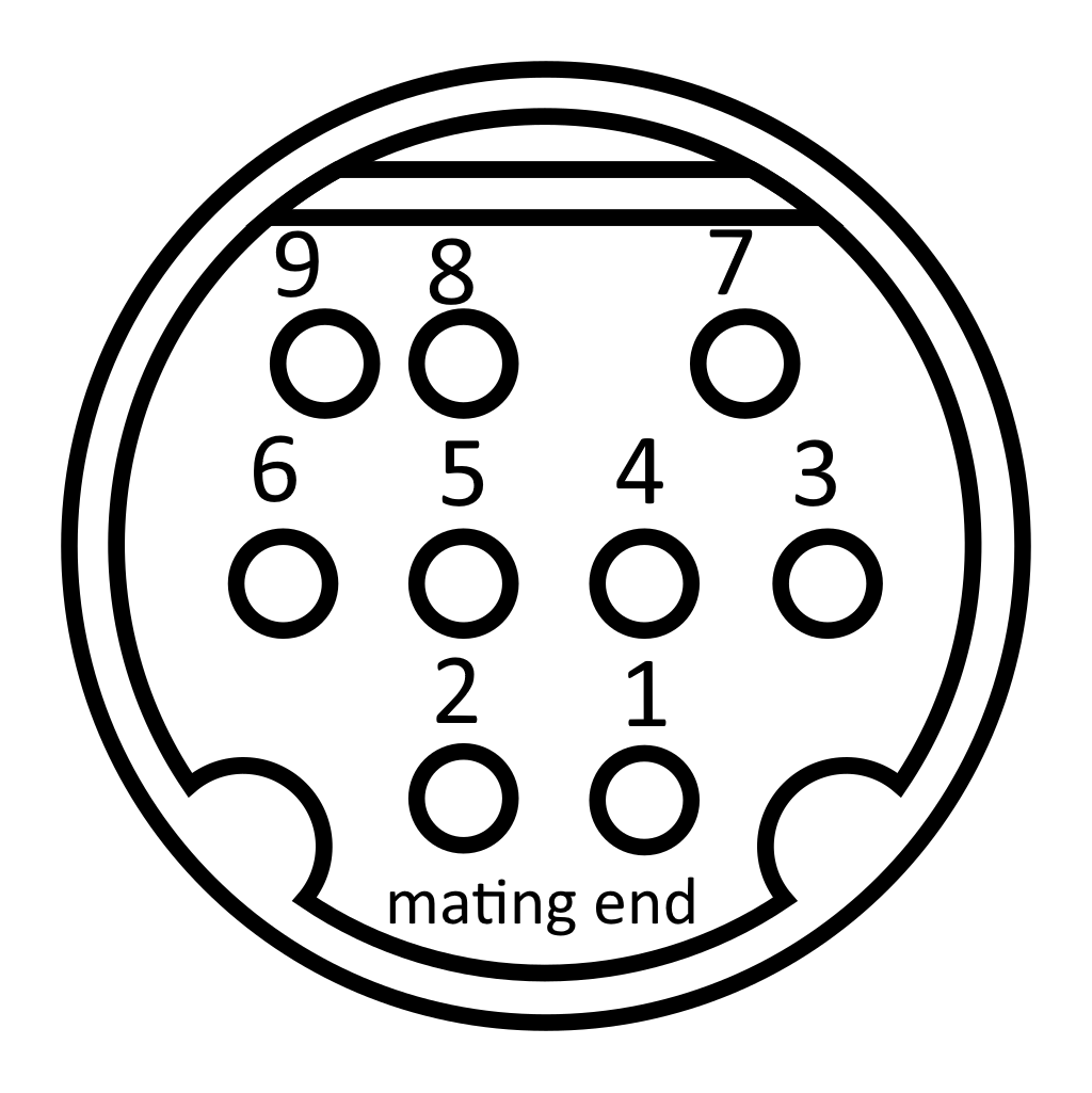
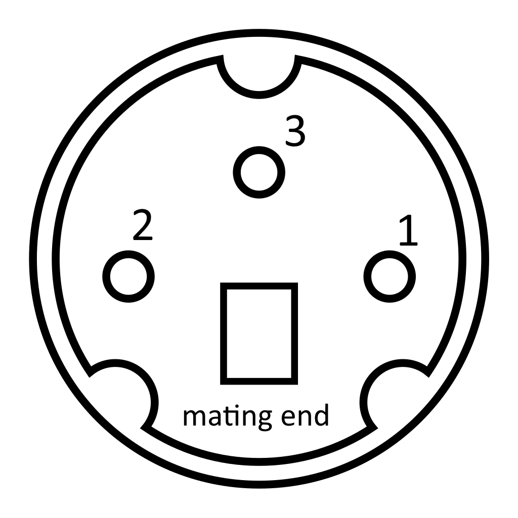
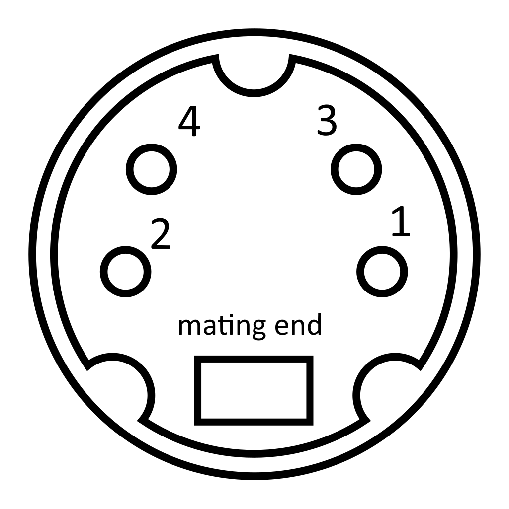
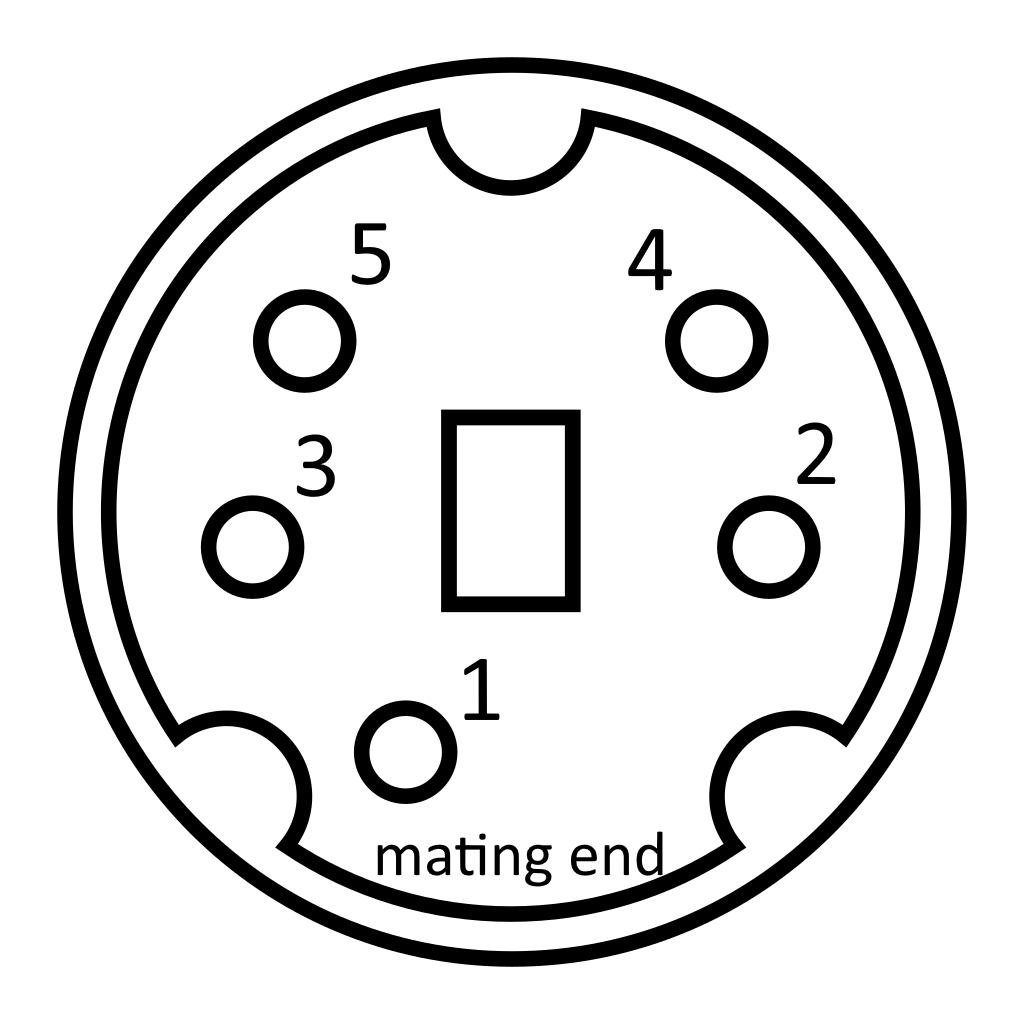
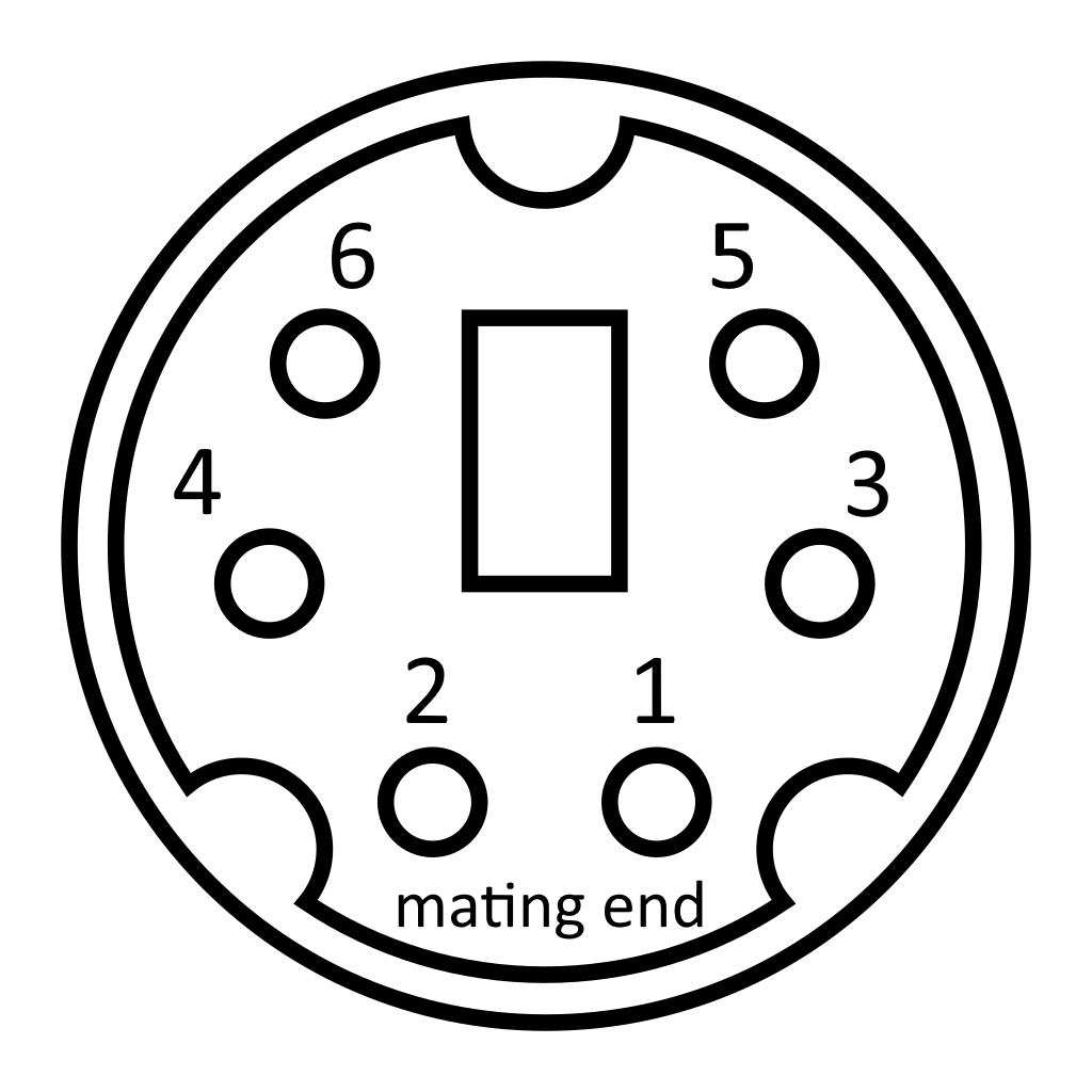
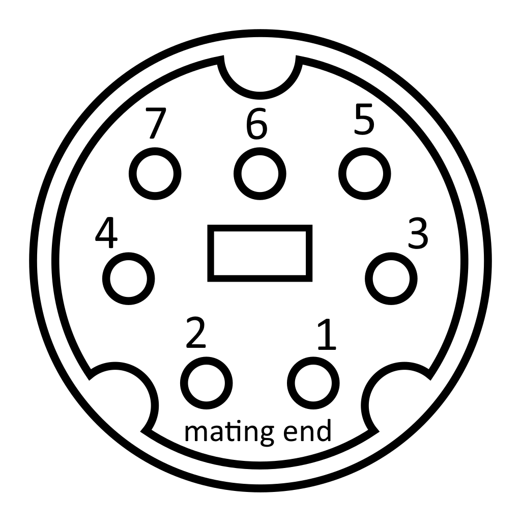
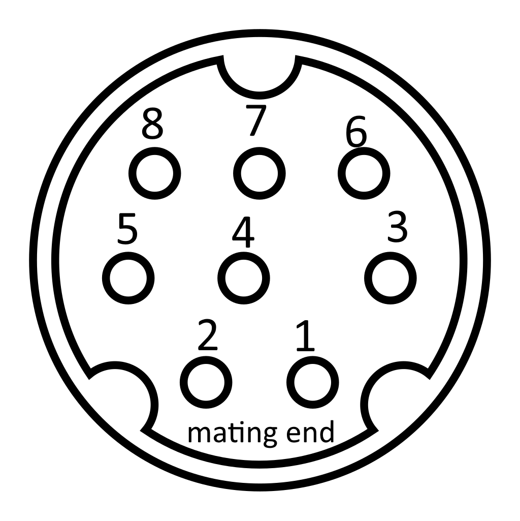
It’s worth noting that the numbering system goes from bottom to top, right to left on the mating side, and left to right on the solder side.
There you have it, let the confusion henceforth cease.
Lance
August 2024
