Many software packages deigned for encoding and decoding RF protocols have the capability of keying a transceiver via serial RTS or DTR lines. Here is a simple design to achieve this with a common USB to Serial TTL adapter.
The Components
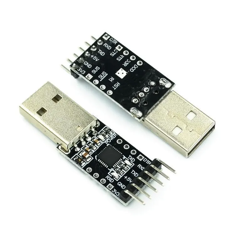
- CP2102 USB to TTL UART Module. Really any module will do, but these are as common as chips, and only cost a couple of dollars each.
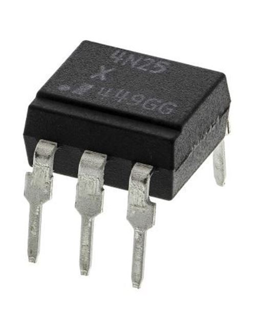
- 4n25 optocoupler. Again, pretty much any optocoupler will do.
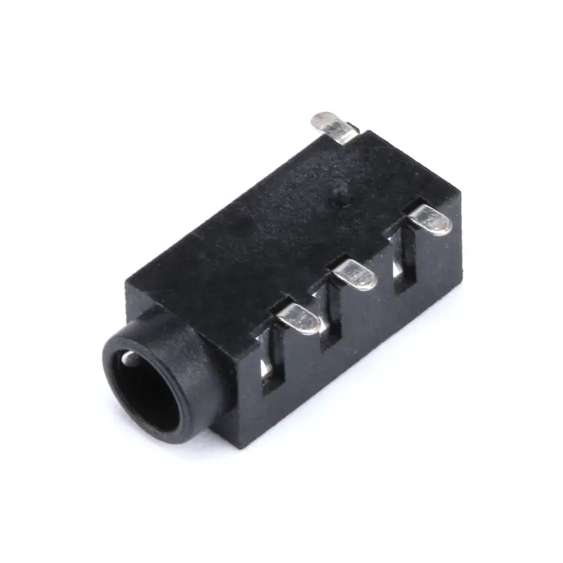
- 3.5 mm headphone socket. You will of course use whichever connector matches your radio interface cable.
- 120 Ω resistor
The Circuit
DTR and RTS lines are supported by most software packages. In my circuit I’m using DTR as my signal line. If preferred, RTS could be used instead.
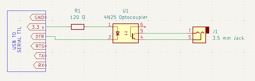
A gotcha if you’re new to Serial TTL flow control; most Serial TTL converters; DTR and RTS are Active LOW. This means when software sets the pin Active, it will have 0 V, and when Inactive, it will have 3.3 v. For our purpose, we want the optocoupler to energise when Active. We can invert the state by using the 3.3 v line for our positive, and the DTR pin to vary our negative voltage. To clarify, consider the truth table below:
| DTR State | 3.3 V | DTR V | Voltage between 3.3 and DTR |
| Active | 3.3 | 0 V | 3.3 V |
| Inactive | 3.3 | 3.3 V | 0 V |
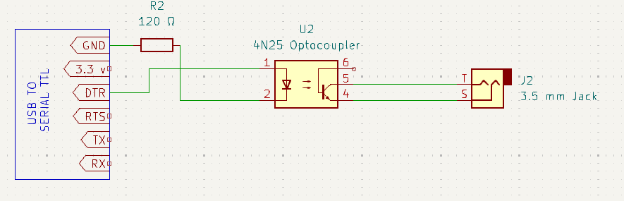
If you somehow ended up with a USB to TTL which exhibits Active HIGH, there is no need to invert, and you can wire it up with GND and DTR.
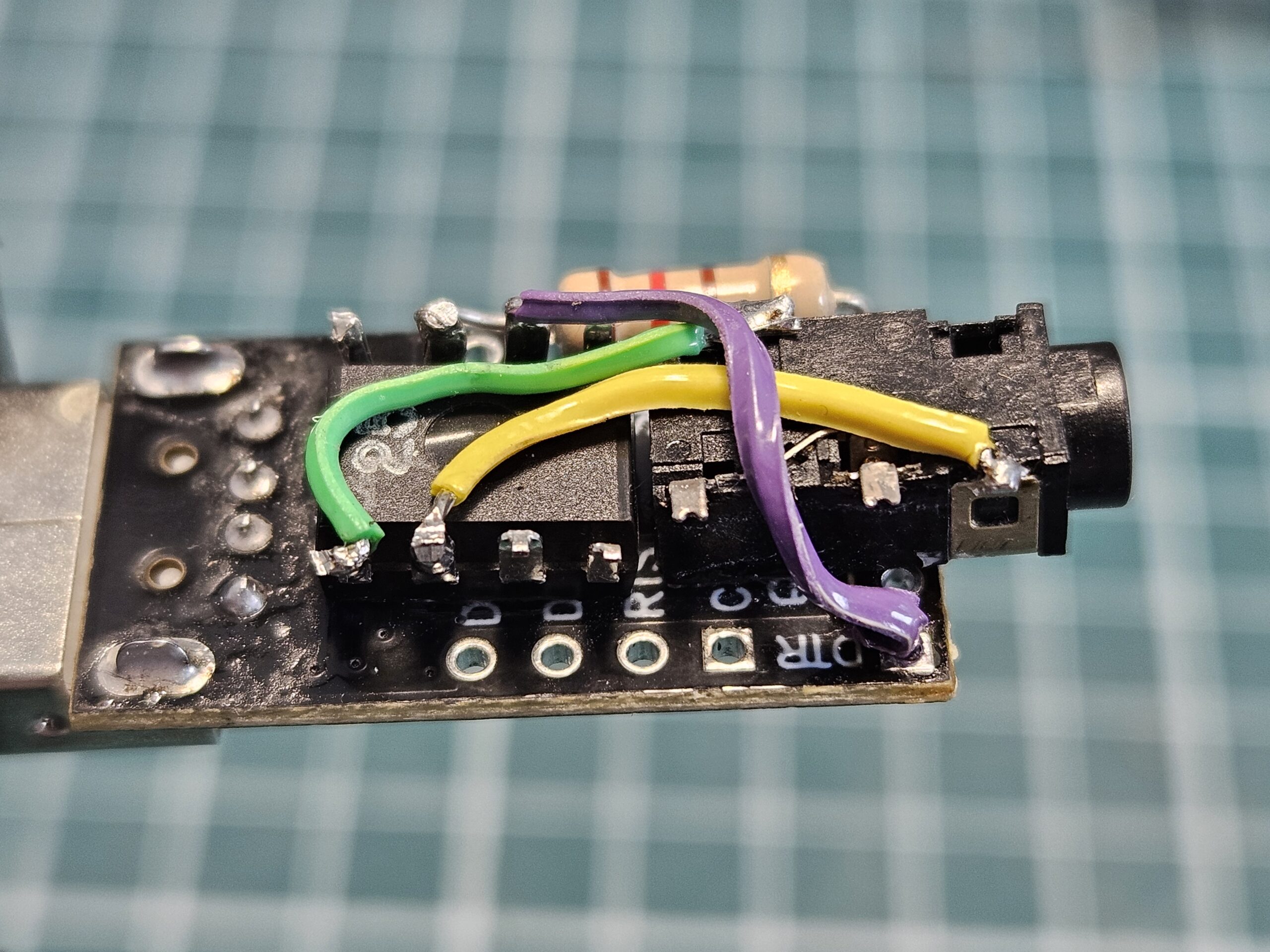
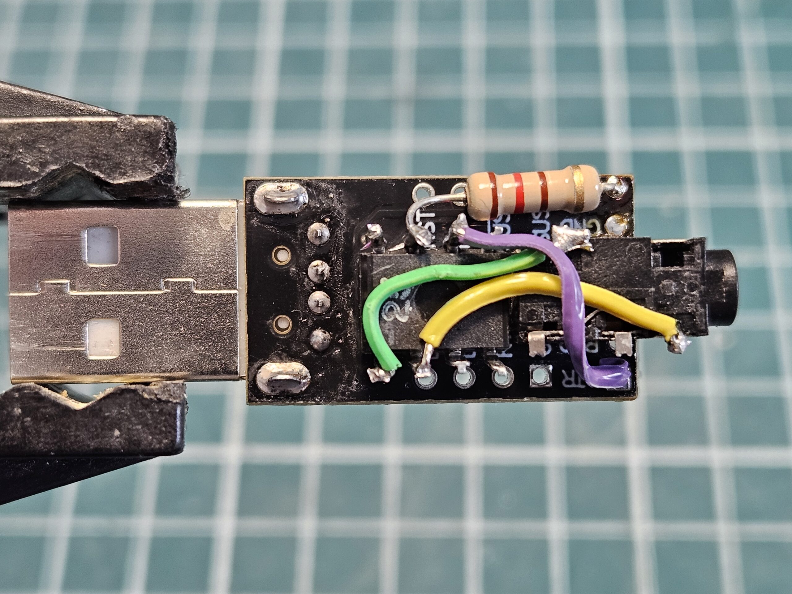
Construction
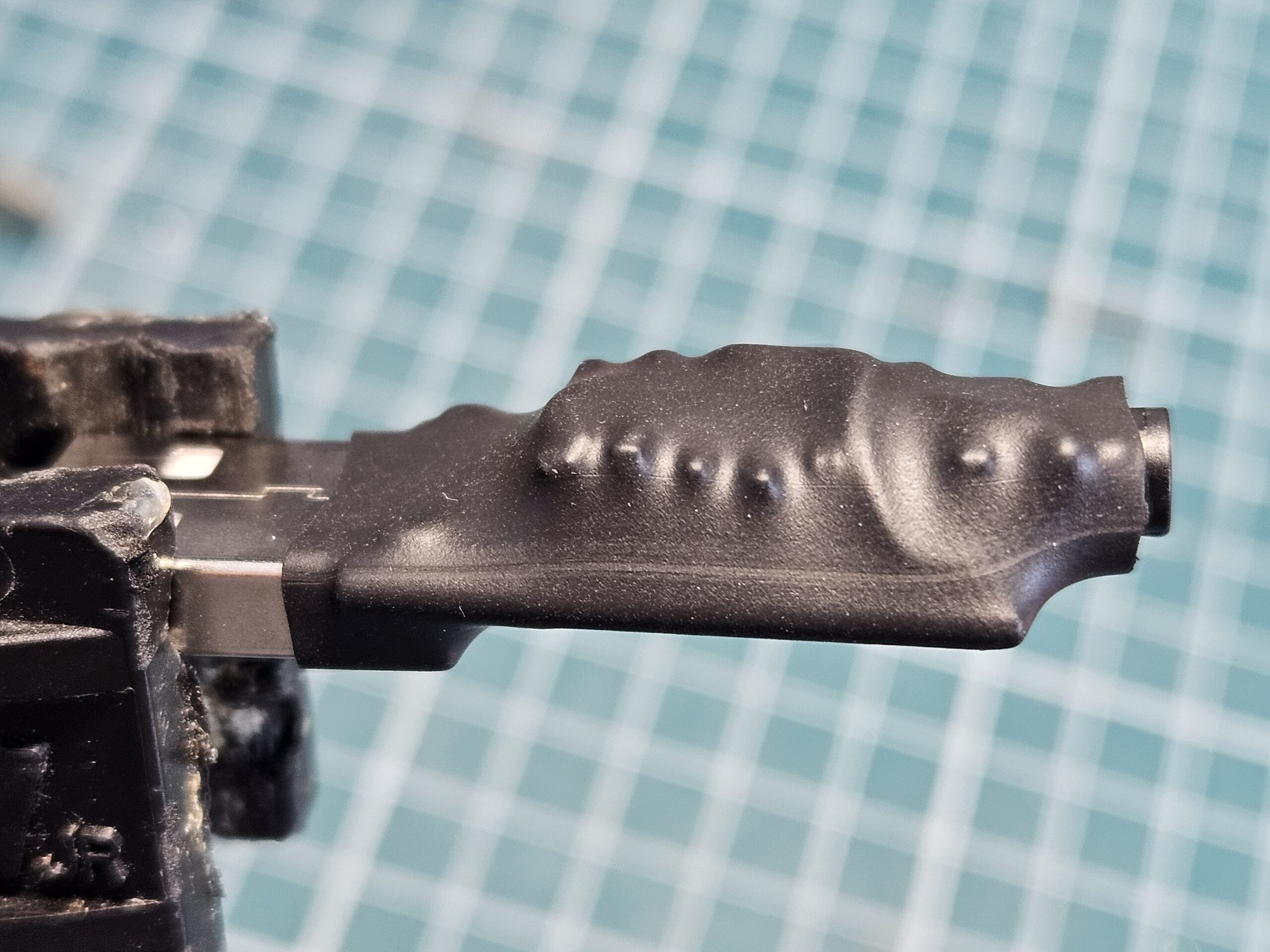
When working with ICs I like to build small components like this dead-bug style; glueing the ICs upside down and soldering directly to their feet. There are no heat dissipation issues, and it creates a nice compact package.
Mine may look a little different as my last 4n25 optocoupler had issues, so replaced it with a 6n138s.
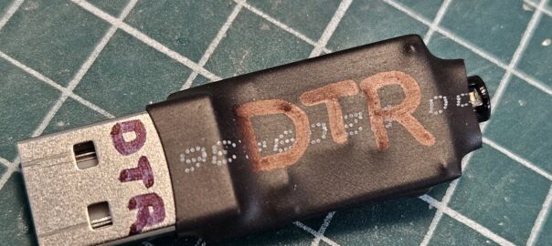
Finishing it off with shrink-wrap offers sufficient protection, as it won’t be handled much at all.
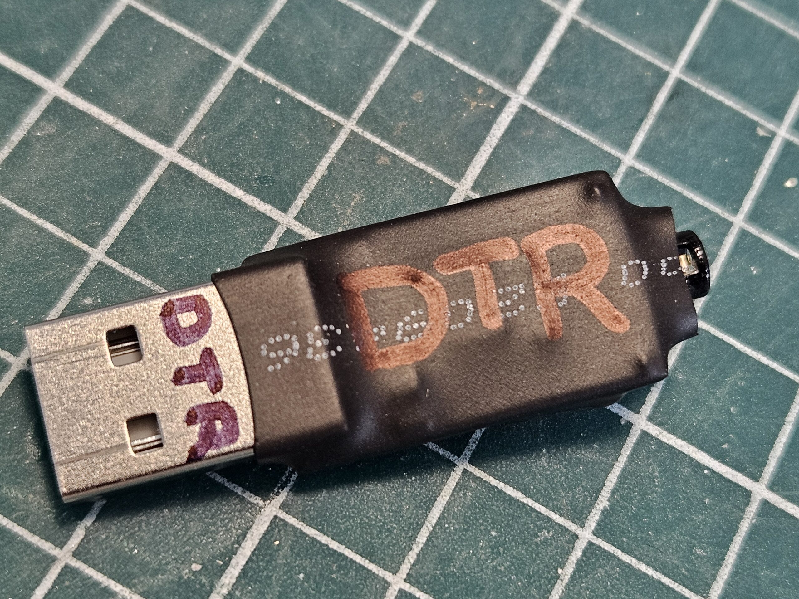
With it all done, the final step was to label it with which signal to tell the software to use, otherwise I would be sure to forget which I used in a couple of weeks.
Lance
September 2024
Resources:
Hi Lance,
Many thanks for the idea on the non inverting DTR idea.. Never occurred to me to use 3.3 and DTR to my opto . I was going to add a transistor to invert it, but this works fine. I have a Ranger RCI 5054 6 meter rig that I have added line in and line outs for FT8. No more need to remove the microphone connection and pull the cable out of the speaker jack to get on phone! Just needed DTR for the PTT.
73’s Jim WA7YEJ
I’m glad it helped, Jim. Good luck with the 6 m openings!
Lance, VK7TO . .