
There is plenty of published information on how to build common mode chokes (CMCs), but not much related to measuring their performance. This post details three such tests using a Nano VNA. If anyone is aware of additional tests which will shed light on a CMC’s performance, I’m all ears.
The three tests I will be detailing are Insertion Loss, Common Mode Attenuation, and SWR.
VNA Setup: Prior to any tests being run, the VNA should be set to the frequency range which you want to test, then calibrated for Open, Short, Load and Through measurements.
Insertion Loss
This measures the signal attenuation when passed through the CMC. A perfect choke would not attenuate the signal at all, whilst an inefficient choke will lose much of the desired signal.
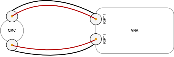
Connections: Port 1 of the VNA connected to one side of the CMC, with Port 2 the other.
VNA: Enable the S21 (LOGMAG) trace.
The VNA should now show the insertion loss across your chosen frequency range.
Chokes which I’ve build exhibit an insertion loss of 0.3 to 0.1 dB across a measured frequency range of 1.5 to 30 MHz, which I consider quite acceptable.
Common Mode Attenuation
This measures the attenuation of common mode current. A perfect choke would attenuate all of the common mode current, whilst an ineffective one would not remove enough to fulfil its purpose.
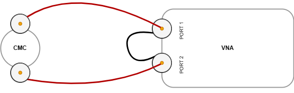
Connections: The centre conductors of Port 1 and 2 are connected to the outer conductors of each side of the CMC respectively. The outer conductor of Port 1 is connected the outer conductor of Port 2.
VNA: Enable the S21 (LOGMAG) trace.
The VNA should show the common mode attenuation across your chosen frequency range. An effective common mode choke should ideally provide a minimum of 20 dB of attenuation.
Chokes which I’ve build exhibit common mode attenuation of 20 to 36 dB across a measured frequency range of 1.5 to 30 MHz.
SWR
When viewed as a single component, a CMC will exhibit a characteristic impedance. It is desirable that it matches the characteristic impedance of components it is inserted between.
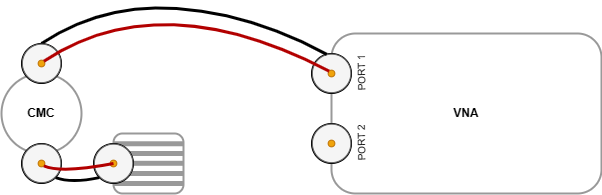
Connections: Port 1 of the VNA connected to one side of the CMC. Connect the other side of the CMC to a dummy load with the desired impedance (probably 50Ω).
VNA: Enable the S11 (SWR) trace.
The VNA should show the SWR of your CMC across your chosen frequency range as close to 1:1 as possible, but certainly below 1:1.5.
Conclusion
I hope that this will arm you with the knowledge to evaluate your CMCs and give you the confidence that they are performing as expected, or if not, build ones that do.
Lance
April, 2024