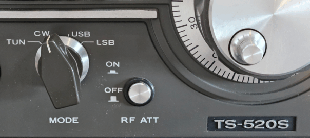
There were some peculiarities with my TS-520s CW operation, and not knowing exactly where the issue lay, I have tried to understand the different factors at play. This post will attempt to demystify the CW signal chain’s frequency transformation.
Note that I’ve named the components based on a combination of user/service manual terms, and the role they perform. As such, the block diagrams later in the discussion are labelled for clarity of understanding, rather than consistency with traditional block diagrams. I’ll kick off the discussion by exploring some of the key components, and then later bring it all together.
The Local Oscillator
Known my many names, including the Local Oscillator (LO), Carrier Generator, and Beat Frequency Oscillator (BFO), this section generates a frequency used to demodulate the signal during receive, or the carrier wave for transmission.
In the TS-520s, there are four distinct LO frequencies for use depending on mode.
| MODE | Receive | Transmit |
| LSB | 3.3935 MHz | 3.3935 MHz |
| USB | 3.3965 MHz | 3.3965 MHz |
| CW | 3.3943 MHz | 3.3950 MHz |
Note that for both LSB and USB, the RX and TX frequencies are the same, whilst CW has a 700 Hz offset between TX and RX. The need for different TX and RX frequencies on CW will be explored in more detail later.
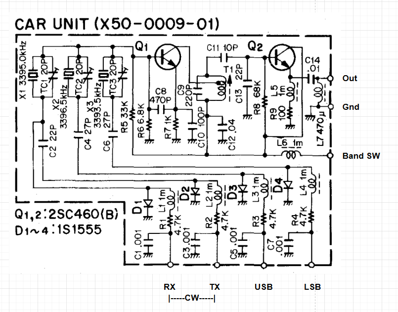
As can be seen from the carrier circuit below, each mode has its own crystal oscillator, with the CW RX bypassing the inline capacitor (C2), resulting in a lower frequency.
Heterodyne Mixer
The heterodyne mixer converts between the on-air frequency at the antenna, and a heterodyne frequency to generate an intermediate frequency (IF) in the range of 8.295 and 8.895 MHz. We’ll call this IF-1. To do this the on-air frequency must be mixed with a different frequency per band, as per the table below. The frequency is determined by the band selection switch.
| Band | Freq. | Band | Freq. |
| 1.8 MHz | 10.695 MHz | 21 MHz | 29.895 MHz |
| 3.5 MHz | 12.395 MHz | 28 MHz | 36.895 MHz |
| 7 MHz | 15.895 MHz | 28.5 MHz | 37.395 MHz |
| 14 MHz | 22.895 MHz | 29.1 MHz | 39.995 MHz |
As you can see, mixing any on-air frequency with its band’s heterodyne frequency will put it in the IF range during RX, and vice versa for TX. e.g.
- 7.100 MHz: 15.895 – 7.100 = 8.795 MHz or 15.895 – 8.795 = 7.100 MHz
- 14.250 MHz: 22.895 – 14.250 = 8.645 MHz or 22.895 – 8.645 = 14.250 MHz
Variable Frequency Oscillator
The Variable Frequency Oscillator (VFO) is responsible for converting IF-1 (8.295 – 8.895 MHz) to the fixed IF of 3.395 MHz, called IF-2.
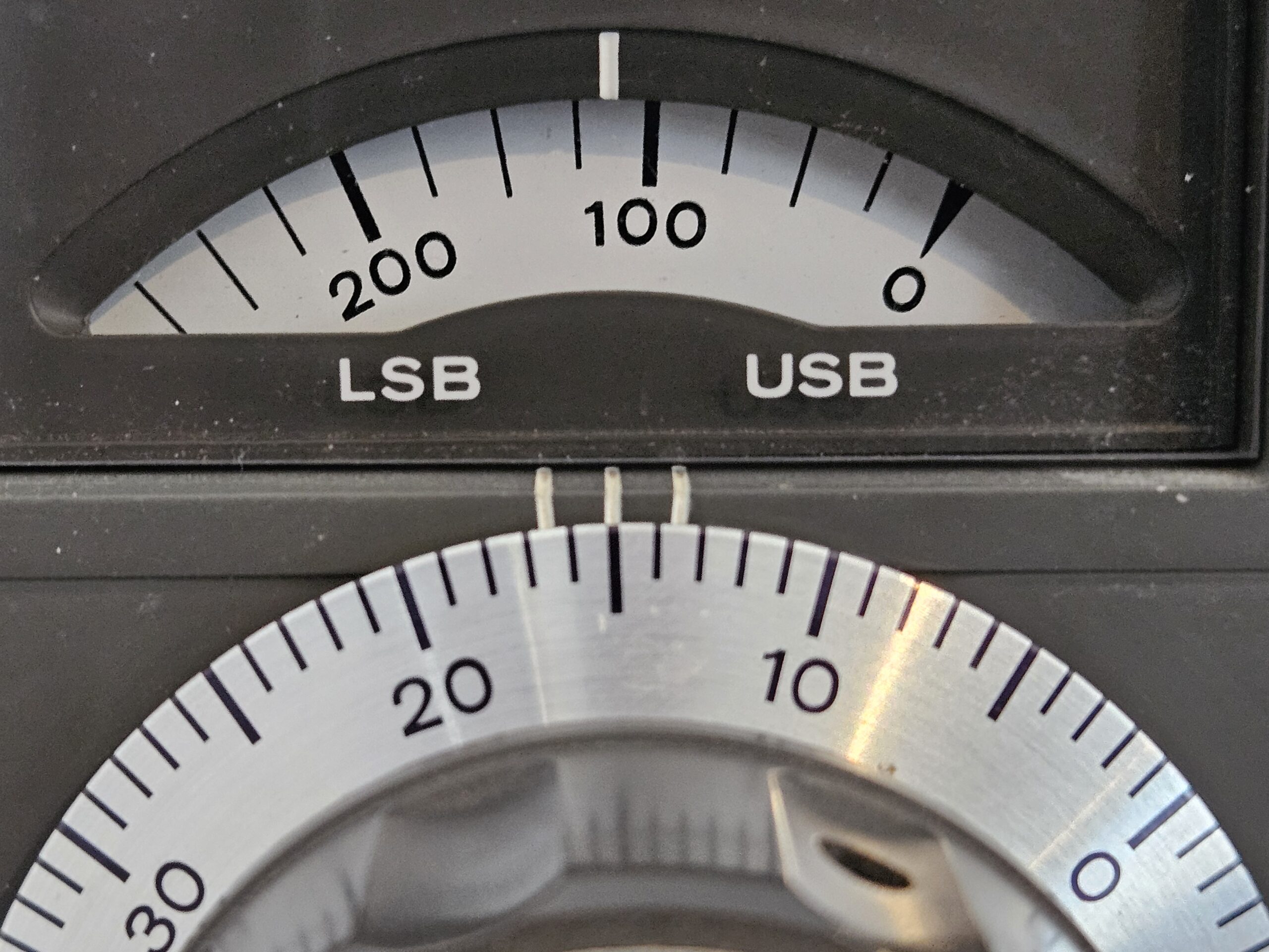
The VFO generates a frequency between 5.5 and 4.9 MHz. The radio’s VFO control has 600 marked graduations. Each graduation represents 1 kHz, with graduation “0” producing 5.5 MHz, and “600” 4.9 MHz. The image below, at graduation 115, corresponds to a VFO frequency of 5.385 MHz (5.500 – 0.115 = 5.385).
Putting it together
Now with a basic understanding of each of our frequency sources, we’ll examine how they’re mixed together in receiving and transmission pipelines. Note that for simplicities sake we are ignoring filtering, amplification, etc.
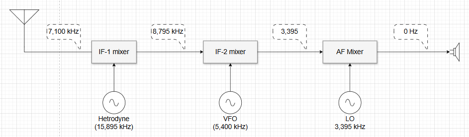
Receiving: Let’s have a look at the receive pipeline for CW with an on-air frequency of 7,100 kHz.
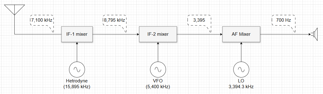
- The 7,100 kHz signal arrives at the IF-1 mixer.
- Because the band switch is set to 40 m, the heterodyne selector provides a frequency of 15,895.
- The heterodyne frequency is mixed with 7,100, resulting in an IF-1 of 8.795.
- The VFO is set to graduation mark 100, therefore outputting a VFO frequency of 5,400 kHz.
- The VFO frequency is mixed with the IF-1, to generate IF-2: 3,395 kHz.
- Because the mode is set to CW and we’re receiving, the LO provides a frequency of 3,394.3 kHz.
- The AF mixer mixes IF-2 and the LO frequency, outputting an audio frequency of 700 Hz. That’s the tone we hear.
Transmitting: Now let’s look at the transmitting pipeline, also for CW with an on-air frequency of 7,100 kHz.
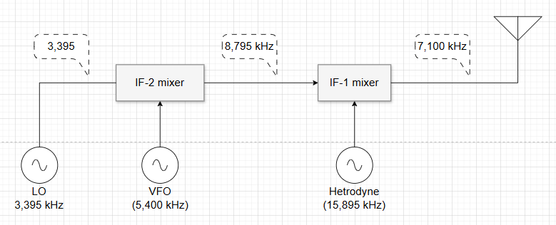
- Because the mode is set to CW and we’re transmitting, the LO provides a frequency of 3,395 kHz.
- The VFO is set to graduation mark 100, therefore outputting a VFO frequency of 5,400 kHz.
- The VFO and LO frequencies are mixed, generating IF-1: 8,795 kHz.
- Because the band switch is set to 40 m, the heterodyne selector provides a frequency of 15,895.
- The heterodyne frequency is mixed with IF-1 to generate the on-air frequency of 7,100.
But why does CW need two LO frequencies?
Let’s examine what will happen if we receive with the LO’s transmitting frequency of 3,395 kHz.
Observe that there is no change until the AF Mixer, at which point we mix the same frequency from the LO and IF-2, giving us 0 Hz, DC, thus no tone will be produced.
If we instead try transmitting with the LO’s receive frequency of 3,395.3 kHz …
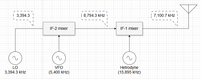
Observe that we are now transmitting on the wrong frequency.
And there you have it, the need for two LO frequencies when operating CW.
Have I got it wrong?
If you notice a flaw in my understanding, I welcome all constructive feedback.
Lance
October 2025